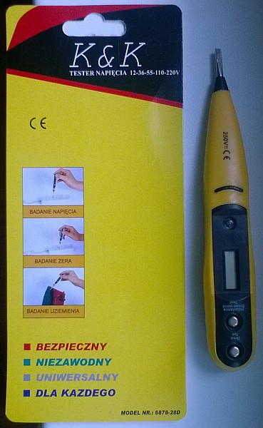
Greetings to everyone. Recently I've bought the tester Made in Poland by "K&K" (not sure what this company or producer is about). It costed me about 4 EURos. The package doesn't have English translation or any other language, so I was forced to re-type this manual by hand and copy/paste to Google Translator for understanding how to use this item. Yes, you must read manuals for such items carefully, because working with 220V voltage always means life risks! Hopefully, it could be useful to someone buying the same tester.
Here are some notes regarding this tester I've gained from my experience.
First of all, before starting using it, you must make sure the electrical device or wire/conductor you're going to test, is under voltage, that is why, I recommend putting the latex gloves, or at least being extremely careful to not touch the bare wires.
I was mostly using it for determining the active phase (voltage ON) or empty phase (NULL or zero) on wires. This is useful if you connect some devices to the internal wiring (like ceiling lamps and so on). Usually, the "NULL" wire is blue, and the "Voltage" wire is brown or red, but there's no strict standard in this. In my case, I was having different color wires, that's why I've bought this tester to determine where's what.
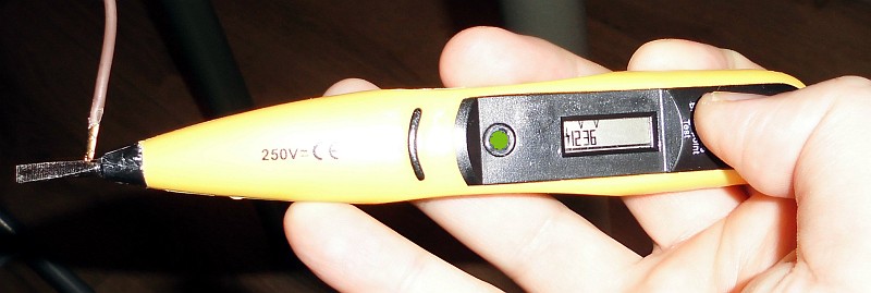
Stick the tester with its sharp end to the bare wire, and then touch either "Inductance Break-Point test" or "Direct Test" button. If you have the "Voltage" wire, holding "Inductance Break-Point test" will light up the led light on the tester. At this time, you may have the "Voltage" sign on the tester's screen, and values 12-32V.
Now hold "Direct Test" button, and you should see all values up to 220V on the screen are visible, and the green led is off in this mode.
Holding "Inductance Break-Point test" should NOT light the green led, and that's the basic sign you have a "Zero" wire. However, at this operation, the tester's screen sometimes could show the voltage sign, and sometimes even add 12V value on the screen. Probably, it's because the Tester is very sensitive and "catches" some electricity field located near the "Voltage" wire in the common flap. I've seen all cases of the NULL wire - an empty screen (ideal), the voltage sign only (weak electricity signal), and the voltage sign with 12V (probably meaning some wrong installation of wiring - still, even such installation could work). So, don't count on the screen while testing the "Zero" wire - the most important that the green led should not light up in this "NULL" wire measuring process.
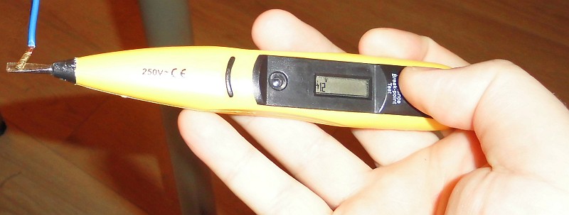
While holding "Direct Test" on the "Zero" wire, there could be shown 12-36V values. Like I mentioned above, this comes from some sensitive point, but it doesn't mean the installation is wrong. Sometimes the tester could show such values because of its sensivity. Ideally, it should show nothing on the screen while holding this button on the "Zero" wire.
Below are attached some pictures with my test results from a regular power socket. The Blue wire is "Zero/NULL", and the Brown wire is "Voltage". The screen shows the values I've described above. Pay attention when the green led is On.
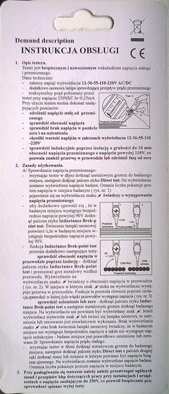
Finally, here's the manual in Polish:
TESTER NAPIĘCIA 12-36-55-110-220V by K&K
1. Opis testera.
Tester jest bezpiecznym i nowoczesnym wskaźnikiem napięcia stałego i przemiennego.
Dane techniczne:
- zakresy napięć wyświetlacza 12-36-55-110-220V AC/DC
- dodatkowo neonowa lampa sprawdzająca przepływ prądu przemiennego
- maksymalny prąd pobierany przez tester przy napięciu 250VAC Is<0,25mA
Przy użyciu testera można dokonać następujących pomiarów:
- odróżnić napięcie stale od przemiennego
- sprawdzić obecność napięcia
- sprawdzić brak napięcia w punkcie zero i na uziemieniu
- określić wartość napięcia w zakresach wyświetlacza 12-36-55-110-220V
- sprawdzić indukcyjnie poprzez izolację o grubości do 10 mm obecność napięcia przemiennego o napięciu powyżej 110V, co pozwala znaleźć przerwę w przewodzie lub odróżnić fazę od zera.
2. Zasady użytkowania.
A/Sprawdzanie napięcia przemiennego:
- trzymając tester w dłoni dotknąć metalowym grotem do badanego miejsca, następnie dotknąć palcem styku "Direct Test". Na wyświetlaczu zostanie wyświetlone napięcie badane. Ostania liczba pokazuje poziom napięcia w miejscu badanym (rys. nr. 1)
- pojawienie się na wyświetlaczu znaku /-/ świadczy o występowaniu napięcia przemiennego
- aby dodatkowo upewnić się, że w badanym miejscu występuje bezpośrednio napięcie powyżej 90V dotknąć palcem styku "Inductance Break-Point Test". Świecienie lampki neonowej potwierdzi, źe w badanym miejscu występuje bezpośrednio napięcie powyżej 90V.
- funkcja "Inductance Break-Point Test" pozwala dodatkowo następujące testy:
** sprawdzić obecność napięcia w przewodzie poprzez izolację - dotknąć palcem styku "Inductance Break-Point Test" i przesuwać grot metalowy wzdłuż przewodu. Wyświetlanie na wyświetlaczu znaku /N/ świadczy o obecności napięcia w przewodzie (rys. nr. 2). W miejscu w którym znak /N/ znika na wyświetlaczu występuje przerwa w przewodzie. Funkcja ta pozwala również poprzez izolacją sprawdzić w której żyle wiązki przewodów występuje napięcia (rys. nr. 3).
** sprawdzić uziemienie lub zero - dotknąć palcem styku "Inductance Break-Point Test" a następnie metalowym grotem dotknąć badanego miejsca. Na wyświetlaczu nie powinien być wyświetlany znak /N/. Jeżeli wyświetlacz wyświetla znak /N/ lub świeci się lampka neonowa, to uziemienie lub zerowanie jest niewłaściwie wykonane. Brak wyświetlania znaku /N/ oraz brak świecenia lampki neonowej świadczy, że w badanym miejscu nie występuje bezpośrednio napięcie a także nie występuje napięcie indukcyjne - badane miejsce jest prawidłowo uziemione lub zerowane.
B/ Sprawdzanie napięcia prądu stałego:
- trzymając tester w dłoni dotknąć metalowym grotem do badanego miejsca, następnie dotknąć palcem styku "Direct Test" a palcem drugiej ręki dotknąć masy lub miejsca w którym powinno być napięcie bieguna ujemnego. Na wyświetlaczu zostanie wyświetlone napięcie badane. Ostatnia liczba pokazuje poziom napięcia w miejscu badanym.
3. Przy posługiwaniu się testerem należy przestrzegać ogólnych zasad i przepisów bhp dotyczących pracy przy instalacjach i urządzeniach o napięciu zasilającym do 250V, co pozwoli bezpiecznie przeprowadzać opisanie wyżej testy.
More references:


testing zero wire - induction
testing zero wire - direct
testing voltage wire - induction
testing voltage wire - direct
 PolishForums LIVE / Archives [3]